TFT Disassembly and Operation
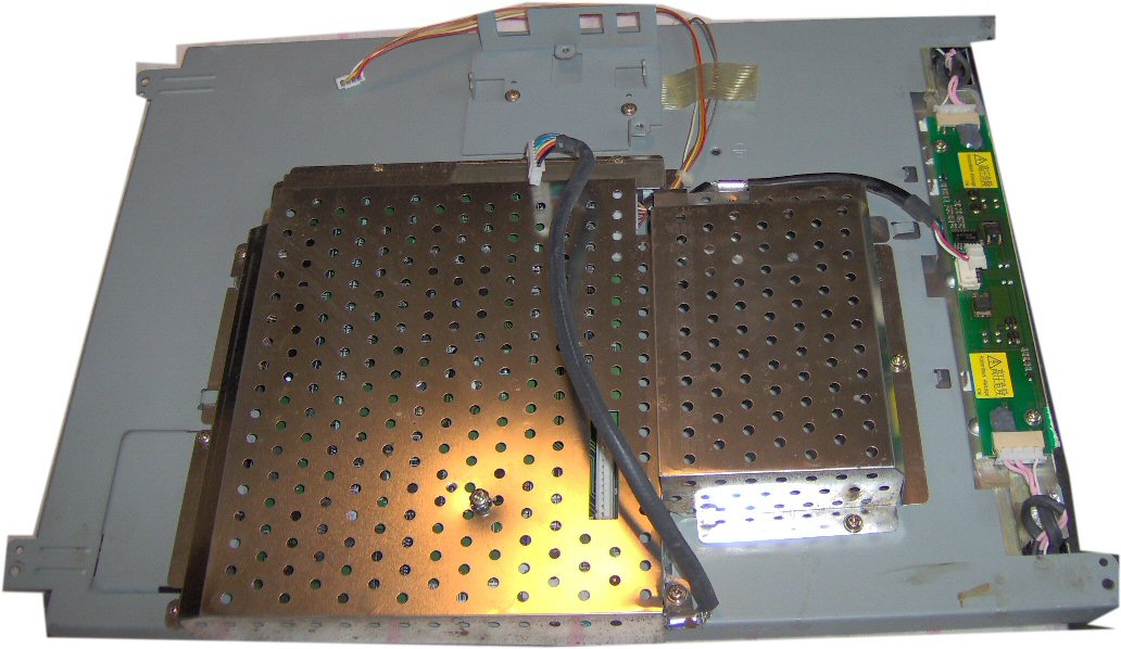 Ok so the outer casing has been removed. The pic on the left shows the back of the TFT. Underneath the tin casing is the power supply unit. This particular unit had a DC input of 12 Volts, but some are 240 Volts mains input.
Also under the tin cover is the "Inverter board." (below) The inverter board creates the high voltage to drive the fluorescent tubes which backlights the monitor. I believe most have two flo tubes, one at the bottom edge and one at the top.
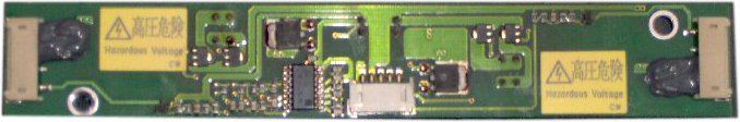 The inverter board (opposite) is the major cause of faults with a TFT monitor. The screen being dark or dim stems from a faulty inverter board. Mainly the onboard transformers or transformer elements burning out. It is also possible for the flo tubes to burn out, but mainly it is a faulty inverter board.
![]() The picture right is a flo tube from a TFT monitor. It is difficult to photograph as it sits within a tin casing and is extremely fragile so didn't want to remove it. Suffice to say it is roughly 5mm in diameter and as long as the screen. In this case the screen was 17 inch so the tube was roughly the same.
The picture right is a flo tube from a TFT monitor. It is difficult to photograph as it sits within a tin casing and is extremely fragile so didn't want to remove it. Suffice to say it is roughly 5mm in diameter and as long as the screen. In this case the screen was 17 inch so the tube was roughly the same.
TFT materials, layer by layer from front to back. Front being the actual screen that you look at.
TFT (Thin FilmTransistor)
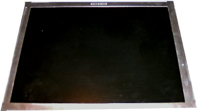
This is the main part of the TFT monitor. It is the TFT. It is about 3mm thick with a printed circuit board on the left and bottom sides.
If you crack this like I did, it is non repairable. If you have black or blank pixels on your screen, this is the cause and is non repairable. If this inherits a fault (for ie: cracked) which makes viewing impossible then again it is non repairable
 .
.
When buying a new TFT monitor, either standalone or laptop, there is always a redundant pixel allowance. This redundant pixel allowance is usually around 2 or 3 pixels and basically the monitor is considered ok if not more than 2 or 3 pixels are "dead" or as described above black or blank. You are quite lucky if you have one without any redundant pixels, I know I haven't.
Behind the TFT
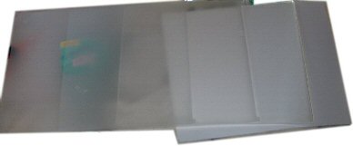
Behind the TFT is 2 sheets of what I can only describe as tracing paper (same size as the TFT). It can certainly be replaced with tracing paper as I have done this with perfect results.
I presume this paper is to remove any glare and evenly spread the illumination delivered by the flo tubes. (will get to next)
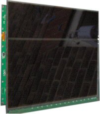
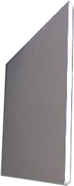 Next comes the Perspex screen. It is roughly about 6mm thick and again the same dimensions as the TFT. It is clear Perspex (although doesn't look it in the picture opposite), and as mentioned earlier, one side has 2 sheets of tracing paper.
On the top and bottom edge lies the florescent tubes. So if you can imagine, the light shines through the edge of the Perspex illuminating the whole area.
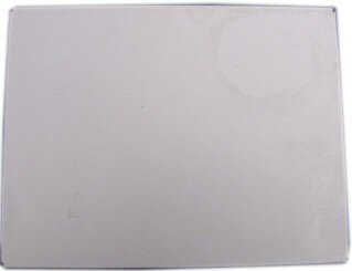 Behind the Perspex is the last sheet. It is a paper thin sheet of white plastic.
The light shines through the clear Perspex, it is reflected by this white sheet, through the tracing paper and TFT.
There's not much more to mention at present. I haven't included some photos like the TFT control board or pictures of the power supply, but that will be in the next chapter regarding TFT power supply problems.
jon rayner 2006